Advanced Passenger Train – APT-P

 Strictly speaking, I should not be running this train on my layout as it is 20 years too late and the Midland Main Line isn’t electrified, but this is my railway and I will run what I want. I fell in love with the train when I first saw it and was so sad that it failed through lack of investment and political cold feet. My model is based on the configuration in use for the trial running in 1984, and I was able to travel on the train from London Euston to Glasgow in March of that year. Each APT-P formation was intended to consist of two half-trainsets, each comprising six articulated trailers: driving trailer second (DTS), trailer second (TS), trailer restaurant/buffet second (TRBS), trailer unclassified for meal services (TU), trailer first (TF), trailer brake first (TBF), and a non-driving motor vehicle (M). The complete formation would be two such sets coupled together (12+2) with their motor vehicles back-to-back in the centre of the train, giving an overall length of 293.88 metres. Traction power was drawn through one pantograph only and there was a 25kV bus line along the motor vehicle roofs connecting the two together.
Hornby produced a minimum-formation 5-car set with a motor bogie in the centre motor vehicle. Apparently they originally considered producing an intermediate first-class coach to extend the set but this did not materialise. The vehicles were good scale models and were also very amenable to being converted to create a full articulated set. I acquired the models as two boxed sets and enough spare parts for four additional vehicles to make up a complete half-set from Blackwells of Hawkwell when they were selling them off as surplus in 1987. I bet they couldn’t believe their luck when I started buying up all their odds and ends. Twenty-two years later, I picked up enough extra vehicles on eBay to make up a full 12+2 car train. When fully assembled, the model will be 12½ feet long – a truly impressive sight!
According to this website, over 15,000 sets were made in the first year of production with the early plain yellow nose and 13,698 (including 980 for Libya!) with the later black window surround and inscription over the following four years until production ceased. I have two pairs of DTSs sporting the alternative nose liveries.
British Rail᾿s in-house newspaper Railnews featured a comprehensive illustrated technical description of the APT in their November 1980 issue and I have used this to guide me in my conversion work. The bodyshell for each of the intermediate articulated vehicles is essentially the same, only the window detail was different for the kitchen area of the TRBS. The Hornby models split horizontally and I realised that if I cut the articulated ends from a DTS and a TF in the right place, they would match up perfectly to give the correct inspection hatch details on both sides. I then had to fit the top part of the TF shell with some very minor surgery and splice the window strips to suit. I then needed to take the first and second class seat units and cut and splice these to give a full car of each. The restaurant car interior was a little different and was made from scratch.
• Pictures and narrative to come on the conversion of the individual vehicles, but click here for a taster.
Since both motor vehicles are coupled together in the middle of the train, I decided to electrically interconnect them to improve the pick-up. The wired coupling for the new Hornby Class 142 is mechanically identical to those on the APT motor vehicle, so these made the improvement very straightforward.
It seemed obvious to power both motor bogies through one decoder by paralleling the motor drive as well. When I installed the decoder, I checked the current draw and found it to be around 1 Amp, give or take. The TCS decoder is rated at 1.3 Amps continuous motor current, so I was comfortably within its limit.
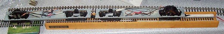
The two motor vehicle chassis connected together under test before fitting the first decoder
However, when I checked the slow running on track, I found that the voltage drop in the wiring to the second motor was such that it would not start turning until after the directly powered motor was under way. So, to give equal power and proper control over the slow running, I had to add a second decoder so as to power each motor bogie directly. The TCS decoders worked in unison perfectly well straight out of the box and I found no need to tweak the performance when I got the whole train out on the main line.
However, when I started adding more intermediate vehicles, I realised that the power to weight ratio wasn’t going to be good enough. The bogie mechanism and wheelbase is the same as the Class 86 loco although that has larger diameter wheels. I found one such bogie at a good price on eBay but others on offer had premium “Buy it Now” pricing which I was reluctant to pay. Eventually I found a complete Class 86 on offer and my successful bid was a lot less than the asking price of the bogie alone! It was a very simple job to retrieve the wheels from the APT dummy bogie and swap them with those from the Class 86 motor bogie. I now have both power cars with two motor bogies each and a dummy Class 86 sitting in a siding, which I’m wondering what to do with. Maybe it will appear occasionally with a steam or diesel pilot on a Sunday diversion away from the WCML wires.
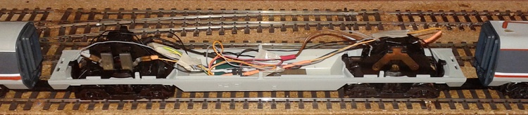
Motor vehicle chassis with two motors electrically connected in parallel.
My thoughts then were to use these decoders to control the train lighting, even though this would mean running additional wires between the motor vehicles and through the train. It would also mean having to use an additional bridge rectifier and relay to feed the interior lights, since a whole train’s worth would exceed the 100mA per function permitted by a standard loco decoder. However, when I realised that I would need six wires each way from the motor vehicles to the rest of the train, I started to think again. The tilting action of the model is delicate and I had visions of the wiring being too stiff to allow this to work smoothly, especially the motor vehicles. There was also the challenge of finding connectors small enough to be inconspicuous but robust enough to do their job.
In the end, I decided to fit additional function-only decoders in each trailer set to control the head and tail lights and the interior lights throughout the train. This means that I can power the interior lighting in each half without using a relay, since these decoders are rated at 200mA per function for each of four outputs. It seemed obvious to put the decoder in the DTS vehicle, since this is where the majority of the lighting functions are needed. I would then need to feed two wires back down the train to power the interior lights, plus two more for the track power input because the leading bogie only picks up from one wheel each side, which would not be reliable enough for the DCC signal. I then realised that, if I ran just one more wire, I could put the decoder in the TBF vehicle which is marshalled next to the motor vehicles, and take my track power from there. This means only two wires are needed between each motor vehicle and the adjacent TBF and the Class 142 inter-car connectors are perfect for the task. The articulated bogies within the trailer rakes mean that a multi-way connector can be accommodated without problem. Another advantage of this approach is that there are only two TBFs, so I only need two lighting function decoders. I have four DTSs, all of which would have needed fitting if I had located them there.
I thought then that I would lose the automatic directional switching of head and tail lights since there are no white and yellow output wires and the four outputs are mapped by default to F1 to F4. However, when I read TCS’s decoder programming guides more thoroughly, they seemed to suggest that any function output could be reconfigured to respond to almost any function button and behave in pretty much any way you might wish, including a whole host of special effects for the American market. After installing the first decoder, I experimented with the CV settings and eventually got the result I was looking for, two output wires remapped to F0 forward and reverse. When added to the motor vehicles as a consist, the whole train behaved perfectly, the NCE PowerCab makes programming and setting up a consist very easy.
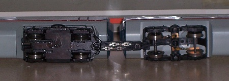
Connection between a motor vehicle and adjacent trailer brake first using the Hornby X8448 coupling
|
|

Connection through an articulated bogie using the DCCconcepts 6-way connector
|
As can be seen from the pictures above, I have transplanted the power pickup bogie from the driving trailer to the TBF to give me a total of 12 axles in parallel collecting power. This gives faultless slow running, even on a less-than-pristine workbench test track.
Because this was the first train I converted to DCC, I was experimenting and learning as I went. That’s the beauty of the system, experimentation with CV settings is non-destructive and, if you get totally lost, you can always apply the factory reset and start again (although I found that this doesn’t reset everything, so it’s important to keep notes of what you’ve done). I later discovered how to implement the decoder locking feature and I reprogrammed them all to the same address, which means that I don’t have to set up a consist. When set up as a consist, every decoder assumes it is going forward when first powered up. That meant that if F0 was pressed before anything else, the headlights would come on at both ends. The direction had to be reversed at least once before each decoder could work out which way it was facing in the consist. There is no such problem when set up to the same address with their direction bits set appropriately as I have them now, the train simply behaves as one unit, just like you’d expect.
• More here on the APT’s lighting
• Back to rolling stock ...