Hornby Dublo Motor Modification
 I have three Hornby Dublo engines in my fleet with the original vertical motor, the Duchess of Montrose and the two 2–6–4 tanks. I also have a ringfield motored shunter that needed similar treatment. Its modification for DCC was not as straight-forward as for a more modern motor because the chassis-return brush holder is embedded in the chassis block. How you deal with this depends on how much you want to preserve the originality of the engine.
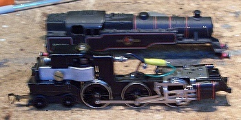
I posed the question on the Yahoo! Hornby Dublo Group and found an established method involving specially made smaller diameter brush tubes and brushes. This avoids the need to permanently modify the chassis and I thought this could only be justified if your engine was in pristine condition and you might want to sell it on as a collector’s item. My models are somewhat play-worn and two of them have been converted from 3-rail to 2-rail, so are already compromised. I have no thoughts of selling them so I felt I could take the easier route as described on this page. Unfortunately, the first picture suffered from camera shake but, since I was recording the work in progress, I can’t go back and re-shoot it!
Both brushes are housed in brass tubes, the front one is insulated from the chassis, the rear one is not and this is where the modification is needed. To get at it, the motor has to be dismantled and the first job is to remove the pole pieces and magnet.
The old iron magnets do not keep their strength like modern materials and fade over time. Be warned, as soon as the magnetic circuit is disturbed, the iron magnet will lose about 70% of its strength and would need to be re-magnetised on reassembly if reused.
Remove the brush retainer plugs, springs and brushes. Unsolder the wires from the front brush retainer plug and from the chassis terminal, and cut the green pick-up feed wire a comfortable distance above where it emerges through the chassis. The old choke and capacitor can be put into your spares box because they are not required after the conversion. These components are designed to suppress radio-frequency interference generated under analogue power. The digital decoder will suppress any such noise and they may confuse the back-emf circuitry if left in. |
|
 |
| Loosen the locknut to the top bearing and remove it, taking care that the small ball bearing doesn’t fall out, then extract the armature. Check for the other small ball bearing in the bottom bearing. |
|
 |
The rear brush tube needs to be driven out backwards. It is delicate and needs treating carefully to avoid damage. I used a three stage process:
- Push flush with the chassis with a flat blade.
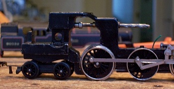
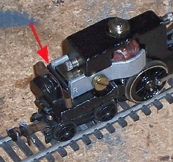
- Insert the blank brush retainer plug into the brass tube and drive it as far as it will go (pictured right). The shoulder is a perfect size to fit in the chassis drilling.
- Retrieve the retainer plug and, using a square ended drift, drive the tube out the rest of the way.
|
|
 |
This is the point of no return where the chassis becomes non-original. Ream or drill out the hole to 4.5mm diameter. Cut a length of plastic sleeving for insulation and insert it into the hole. The standard plastic insulating sleeves available from Wrenn spares stockists are too short for this and need an even larger diameter hole.
Push the brass tube into the insulation sleeve and on into the chassis block. This takes a bit of trial and error to get right, since the insulating sleeve will get dragged into the chassis with the brass tube. It needs to be cut long and then trimmed to length when you have the brass tube in the right place. The insulation needs to be about 0.5mm proud of the chassis and the brass tube just proud of that. |
|
 |
Before going any further, TEST the insulation! There must be no electrical connection between the brush tube and the chassis. Any mistake here will mean instant death for the decoder when power is applied!
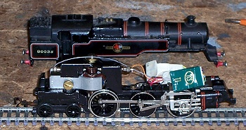
If all is well, insert the armature and top bearing, with a drop of light oil top and bottom. Check to make sure the small ball bearings haven’t gone missing. Connect the decoder leads: red to the lead from the pick-ups (with sleeving over the joint), black to the chassis terminal, orange to the front brush retainer plug, grey to the rear brush retainer plug. The other wires must be coiled and taped up out of the way, paying especial attention to the blue wire which is live at all times and must not come into contact with any other wire. No wire must be allowed to come into contact with any other metal part.
Reassemble the magnet and pole pieces, I used a new Neodymium magnet which avoided having to get the original re-magnetised. Replace the brushes, springs and retainers. Fit the decoder into its connector and tuck it up into the boiler when replacing the body. Track test and configure the decoder to your preference. If the engine goes the wrong way then the magnet is the wrong way round. You can either reverse the magnet or reverse the direction bit in CV29. |
|
 |
The 2-6-4 tank engine was fitted with an adjustable steel plate which acts as a magnet shunt. The engine is fitted with the same armature as the Duchess class engine and has a lively turn of speed. The magnet shunt was Meccano’s answer to slow it down to a more realistic speed and it also improved the starting torque by reducing magnetic locking or cogging. It could be adjusted through a hole in the back of the bunker. Unfortunately, it also had the effect of reducing the engine’s power. TCS’s superb back-emf control completely overcomes any tendency for magnetic cogging and, by adjusting the appropriate CVs in the DCC decoder, the top speed can be tamed without sacrificing the power, so the shunt can be omitted.
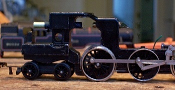
As can be seen here, the rear brush retainer plug is perilously close to the magnet and prudence suggests that a piece of sticky tape be placed between the two for insulation – just in case! |
|
 |
In conclusion
The cost of the modification is virtually nil and you are still using standard brushes and springs. The only new part needed is the insulating sleeve and I used a length of heat-shrink I had in my spares box that happened to be the right diameter. You then add your choice of decoder. There was plenty enough room to install a DCC decoder and the new Neodymium magnet will improve the engine’s performance giving more pulling power at a lower current, and it will retain its strength indefinitely.
• Back to previous page