Midland Pullman Conversion
This page archives the conversion work I started on my old Triang Blue Pullman cars before succumbing to a late-night purchase of the Bachmann set on eBay.
Conversion Work
I bought a complete set of etched brass window frames from Southern Pride Models for the conversion and was surprised to see how much they had compromised the scale of the parts to fit the Triang power car window apertures. After much thought, I decided to use the etchings only for the kitchen cars. Even these needed modifying as they are based on the Western Region kitchen cars, those for the Midland Region were very slightly different. I re-sold the others on eBay for rather more than I originally paid! The driving cab windows and the door windows throughout are flushed with South Eastern Finecast glazing and all vehicles have new branding and numbering from Fox Transfers.
Triang only made one moulding for the underframe, it was a good representation of the power cars but they took a huge liberty in using it for the parlour car as well. Thus the underframe detail to both the kitchen and parlour cars would need extensive alteration. Triang also used their standard BR1 coach bogies for the vehicles and, because of the integral couplings, they were too close to the ends. The pivot points would need to be moved towards the centre of the vehicles and the bogies dealt with. I found that I needed to adopt a different method for the power cars and the other vehicles as described below.
I spoke with someone who was exhibiting a converted Blue Pullman Set at a show and asked him why he had not changed the underframe detail. His answer was simple: because he could not be certain of all the detail of the various elements of the underframe, he thought it best to do nothing! In my humble opinion, that is a recipe for defeat and a rather lame excuse. As I have said earlier, the model is already a compromise, so I took the view that a model based on the best available information is better than accepting something that is obviously wrong.
Power Car
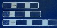 The most visible modification to the power cars was to change the windows to suit the wider pitch of the first class seating. The window apertures needed to be lengthened by about 5mm overall and I adapted the windows displaced from the kitchen cars to give a truer window spacing. At the top here is the original second class window strip, at the bottom is part of the strip from the first class parlour car, and in the middle is the new first class window strip. The most visible modification to the power cars was to change the windows to suit the wider pitch of the first class seating. The window apertures needed to be lengthened by about 5mm overall and I adapted the windows displaced from the kitchen cars to give a truer window spacing. At the top here is the original second class window strip, at the bottom is part of the strip from the first class parlour car, and in the middle is the new first class window strip.
 I took spare first class seating units displaced from the kitchen cars and lined them up with the new windows. The bulkheads were taken from the redundant second class seating mouldings. I took spare first class seating units displaced from the kitchen cars and lined them up with the new windows. The bulkheads were taken from the redundant second class seating mouldings.
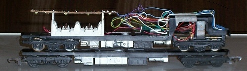 A less obvious but unavoidable modification was that the whole of the underframe moulding needed to be moved up to accommodate the relocated bogie pivot point and the longer wheelbase. Triang had condensed the gap to suit the short bogie. So I made a cut forward of the battery boxes and removed 6mm. When reassembling, the battery boxes overlapped the cut and I had to slightly foreshorten the air cylinder. I cut off the saloon end of the floor and replaced it with a section 6mm longer cut from a spare underframe. The end portion I removed was then used to similarly replace the end cut off the second power car. This picture shows the modified power car placed on top of an unmodified underframe to show the difference. Note that the power bogie is more or less in the right place. A less obvious but unavoidable modification was that the whole of the underframe moulding needed to be moved up to accommodate the relocated bogie pivot point and the longer wheelbase. Triang had condensed the gap to suit the short bogie. So I made a cut forward of the battery boxes and removed 6mm. When reassembling, the battery boxes overlapped the cut and I had to slightly foreshorten the air cylinder. I cut off the saloon end of the floor and replaced it with a section 6mm longer cut from a spare underframe. The end portion I removed was then used to similarly replace the end cut off the second power car. This picture shows the modified power car placed on top of an unmodified underframe to show the difference. Note that the power bogie is more or less in the right place.
Triang made the buffer beam to the power car cab ends higher than scale to clear their couplings. Genesis produce castings to replace the cab ends but I decided not to use these. Careful measurement suggested that the buffers were only 2mm too high and I decided that I could live with the discrepancy, I reckoned that I didn’t need the extra work.
Both power cars have a Triang motor bogie fitted with new wheels and a decoder. I have replaced the old Triang magnets with new Neodymium magnets to improve the train’s performance. Each decoder controls the head and tail lights of its own vehicle as well as the interior lighting for that half of the train. More here ... |
Parlour Car
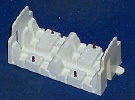
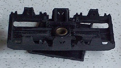
  The underframe detail for the parlour cars is relatively sparse, all the existing equipment mouldings were removed and the required items replaced. Adjusting the bogie pivot positions was done differently than for the power cars. I cut across the underframe either side of the pivot and reversed that portion. The precise distance of the cuts from the pivot is not critical but the difference is, it needs to be 6mm. I marked at 10mm and 16mm. The cuts need to be truly square across the underframe as well as parallel to each other as shown in the pictures here. The underframe detail for the parlour cars is relatively sparse, all the existing equipment mouldings were removed and the required items replaced. Adjusting the bogie pivot positions was done differently than for the power cars. I cut across the underframe either side of the pivot and reversed that portion. The precise distance of the cuts from the pivot is not critical but the difference is, it needs to be 6mm. I marked at 10mm and 16mm. The cuts need to be truly square across the underframe as well as parallel to each other as shown in the pictures here. 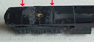 The cut portion of the underframe is reassembled the opposite way round so that the pivot point is repositioned. I added an offcut of sheet polystyrene inboard of the pivot to reinforce the inner joint and the Keen Close Coupling base reinforced the outer joint. The cut portion of the underframe is reassembled the opposite way round so that the pivot point is repositioned. I added an offcut of sheet polystyrene inboard of the pivot to reinforce the inner joint and the Keen Close Coupling base reinforced the outer joint.
The parlour cars have their original window strips repainted, since the etched brass frames gave no significant improvement.
• More pictures to come ... |
Kitchen Car
Kitchen car conversions occasionally come up for sale on eBay and go typically for £100 plus. Some of the conversions have replacement bogies but I have seen none with the corrected underframe detail, which is a shame. As for the parlour car, the existing mouldings were removed with a razor saw and those items required were stuck back in the appropriate places. 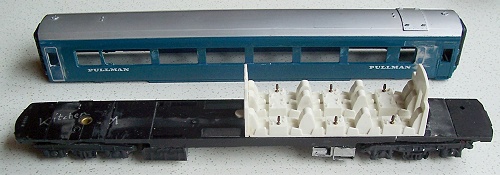 The extra items, such as the auxiliary gen-set, were made up from bits and pieces from the spares box. I also had to adjust the bogie pivot positions using the same method as for the parlour car. The extra items, such as the auxiliary gen-set, were made up from bits and pieces from the spares box. I also had to adjust the bogie pivot positions using the same method as for the parlour car.
The seating was cut in half and the end bulkhead moved as can be seen in the picture on the right here.
The etched brass window frame needed to be shortened on one side and the bodywork was infilled with a piece cut from a spare shell.
|
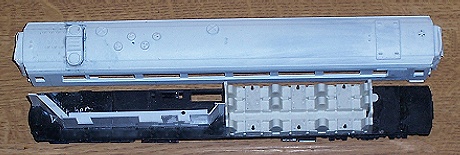 The roof detail was a bit more problematic. After studying available photographs of the prototype and comparing these with the Kitmaster model, I thought I would be able to build this from bits from my spares box. I found that the Vent Axia cowls made by MJT Scale Components (from Dart Castings) for the BR Mk1 catering vehicles were just right for the two larger extractor cowls. Then, when checking my web links towards the end of October 2010, I found that Southern Pride Models had set up a new website. I also found that they had introduced a kitchen car roof detail pack with all the ventilators and extractor fans. I think that the kit is a very reasonable attempt at getting the details right, the picture here shows the modified roof in primer, above the interior with the kitchen corridor partition added. Since the windows to the kitchen area are frosted, interior detail will be superfluous. The roof detail was a bit more problematic. After studying available photographs of the prototype and comparing these with the Kitmaster model, I thought I would be able to build this from bits from my spares box. I found that the Vent Axia cowls made by MJT Scale Components (from Dart Castings) for the BR Mk1 catering vehicles were just right for the two larger extractor cowls. Then, when checking my web links towards the end of October 2010, I found that Southern Pride Models had set up a new website. I also found that they had introduced a kitchen car roof detail pack with all the ventilators and extractor fans. I think that the kit is a very reasonable attempt at getting the details right, the picture here shows the modified roof in primer, above the interior with the kitchen corridor partition added. Since the windows to the kitchen area are frosted, interior detail will be superfluous.
• More pictures to come ... |
Bogies
The prototype was fitted with bogies based on the Swiss Schlieren design which were very distinctive. There are two types: the bogies to the power cars and the adjacent end of the kitchen cars had a wheelbase of 9'-6" whilst the bogies under the parlour cars and the adjacent end of the kitchen cars were unpowered and had a wheelbase of 8'-6". Triang had used their standard 8'-6" BR1 coach bogies for all except the motor bogie in the power car, which was somewhere between the two.
I bought a set of pewter castings by Genesis for the powered bogies and by Chris Leigh for the unpowered bogies, since Genesis hadn’t produced theirs at the time I was buying. The Genesis bogie kit is highly detailed, it includes a whole host of brake gear details that would become invisible once installed under the vehicle and, at first glance, seemed fearsomely complicated and difficult to assemble. By comparison, Chris Leigh’s kit for the unpowered trailer bogie was very basic. However, when I came to clean up the castings ready for assembly, I found all sorts of problems. In comparison with the Genesis kits, they needed considerable work with a file to make the parts fit together and I found that one sideframe was porous and broke in two when I started to clean it up. However, the main problem was that the stretcher castings were made too short! I would have had to perform serious surgery to create sufficient clearances get the wheels in. After much heart-searching, I decided to take the easy option and ordered replacements from Genesis, who now have complete sets of both types in their range.
The clear moral of the tale is to check your purchases immediately they arrive so that a refund can be requested if they’re not up to the expected standard.
Whilst trying to work out how to assemble the parts, I was particularly baffled about how I would ensure that everything remained square and true whilst setting. The added difficulty was that the wheels would have be be included in the assembly since they would be captive within the rigid casting. Inspiration came from Jackie Daines who got in touch through these pages and told me about the way she had adapted the Triang bogies for a similar conversion she was working on. Like all great solutions, hers was elegantly simple. She had adopted more or less the same method that I had adopted for the two motor bogies and I am indebted to her for her contribution.
Original Motor Bogie
  The wheelbase of the Triang motor bogie was 1.5mm short of scale and the Genesis castings were 0.5mm short of scale, so I reckoned that I could simply apply the Genesis side castings to the Triang bogies without the error being apparent. I filed the incorrect detail off the sides of the Triang bogies and adjusted the silhouette around the axleboxes with a file. After cutting the lug from the Genesis side casting I filed as much metal off the inside as I dared to reduce the overall thickness. There is a convenient moulding flash around the edges which I used as a witness line. The technique I found worked best for me was to rub the sideframe up and down a file laid flat on the workbench. I used leather work gloves to help grip the casting without ruining my finger tips on the file. I then simply Araldited the pewter to the Triang bogie sides as shown on the left. The picture on the right is after painting and re-wheeling. The wheelbase of the Triang motor bogie was 1.5mm short of scale and the Genesis castings were 0.5mm short of scale, so I reckoned that I could simply apply the Genesis side castings to the Triang bogies without the error being apparent. I filed the incorrect detail off the sides of the Triang bogies and adjusted the silhouette around the axleboxes with a file. After cutting the lug from the Genesis side casting I filed as much metal off the inside as I dared to reduce the overall thickness. There is a convenient moulding flash around the edges which I used as a witness line. The technique I found worked best for me was to rub the sideframe up and down a file laid flat on the workbench. I used leather work gloves to help grip the casting without ruining my finger tips on the file. I then simply Araldited the pewter to the Triang bogie sides as shown on the left. The picture on the right is after painting and re-wheeling. |
I worked on the other bogies after I had cut the underframe floor and before reassembly, which made them a lot easier to handle.
Short Wheelbase Bogie
 I filed all the detail from the bogie sides and removed the stretchers between the axleboxes. The bogie sides are now 2mm thick and the axle bearing holes are showing through. Since these bogies are 40 years old, some of them are the worse for wear and the bearing holes decidedly ragged. I would be fitting new wheelsets, so it seemed only right to fit brass axle bearing cups whilst I had the opportunity.
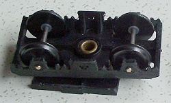 I used a hot soldering iron to push the brass bearings into the holes in the sideframes, they will come right through. I used flanged bearings which gave a larger surface to adhere to the plastic and these needed to go flush with the inside face of the bogie. Check by inserting a wheelset which should spin freely with no side-play.
The bearings I used had little turning pips on the ends which needed to be filed off after everything had cooled down. The melted plastic residue also needed to be cleaned off.
 I reduced the thickness of the cast metal sideframe using the same method as for the motor bogie. The axle bearing holes in the metal castings were drilled out to clear the brass bearings, a loose fit is fine here, and I superglued the castings to the plastic bogie. Even though superglue is supposed to be instant, I felt it prudent to allow the assembly to set overnight before handling it again.
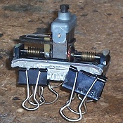
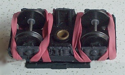
 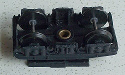 The Royal Mail’s red elastic bands hold everything together whilst the glue sets.
The picture on the right shows that I still have some fettling to do to remove excess plastic to match the profile of the new bogie sides.
I found that it was just possible to insert the wheelsets after gluing the new sides to the bogies. I also found that it was a lot easier to insert them beforehand, so that’s what I did after the first one.
Long Wheelbase Bogie
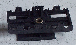
 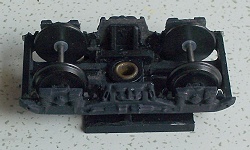 Before applying the cast metal sides, the bogies need to be stretched by 4mm, which I did after filing off the moulded side detail. I marked one side so that I would know which way round it had to go back and then cut each side of the centre pivot boss. I cemented a 2mm thick shim to each of the outer ends and allowed them to set overnight before trimming the width and thickness to match the original. Then I cemented the shimmed ends to the centre portion and allowed to harden. As a precaution, I reinforced the joints with square-section sprues. Compare these pictures with those of the short wheelbase bogie above. Before applying the cast metal sides, the bogies need to be stretched by 4mm, which I did after filing off the moulded side detail. I marked one side so that I would know which way round it had to go back and then cut each side of the centre pivot boss. I cemented a 2mm thick shim to each of the outer ends and allowed them to set overnight before trimming the width and thickness to match the original. Then I cemented the shimmed ends to the centre portion and allowed to harden. As a precaution, I reinforced the joints with square-section sprues. Compare these pictures with those of the short wheelbase bogie above. |
Fitting the metal sides to the bogies has resulted in a useful increase in weight right down at wheel level, which should significantly improve stability when running.
Couplings
I removed the Triang couplings from the bogies and fitted the Keen Close Coupling System between the vehicles. Here is a trial fitting with Roger Keen’s scale buckeye coupling with the bogies temporarily removed.
|
|
 |
• More here on the Pullman’s lighting.
• Back to rolling stock ...