It is perfectly possible to power a complete railway layout through one large booster and nothing else, but that would not be very sensible. For the same reason that your home electrical system has a consumer unit (fusebox) with several fuses or circuit breakers to subdivide the supply, so it is better to have the layout divided into a number of power districts. The conventional way to do this is to include a number of sub-district cutouts. Thus, if there is a problem anywhere on the layout, only the affected part shuts down and the fault current can be limited to a safer value.
Commercially available boosters are normally rated at either 5 or 10 Amps, which can do a lot of damage very quickly in the event of a derailment or other fault. Some modellers use current limiters in the form of 12 Volt car light bulbs wired in series with a feed wire to protect their sub-districts. This is, in my view, a hang-over from the simple train-set controller where the overload light was in the controller and was immediately obvious. The current into the fault was limited to a safe level even if the controller wasn’t turned off whilst the problem was investigated and corrected. With DCC, a high current will continue to flow through the pickups and wheelsets of whichever vehicle has run into trouble and the web is full of pictures of expensive models melted beyond redemption! So my view is that, if you have an overload, it’s probably a short circuit and the power needs to be cut as soon as possible.
However, things become more complicated with sound decoders, since many of these have a high in-rush current when powered up which, when several are invloved, is hard to distinguish from a short circuit. I regard this as a design oversight by the decoder manufacturer, all it needs is a simple resistor and diode (costing a couple of pence) to limit this current.
Something to remember is that if a short circuit is a short circuit, rather than a marginal overload, then the full current available from the main booster and power supply will flow until a cutout trips. There has to be a time delay before the main booster trips because the sub-district cutouts need to be given time to register the overload and react first. If not, then the whole layout will stop every time. Most commercial boosters and cutouts automatically re-try at intervals and, if this goes on for more than a couple of minutes, things will get very hot.
Many people say that the most common cause of a short-circuit (apart from a derailment) is trying to run through a turnout that’s not set correctly. This will trip the power and, if your accessory decoder is powered off the same curcuit, you will not be able to move the turnout to clear the short. I am using MERG accessory decoders for my turnouts, signals, and other auxiliaries, which are designed to run off a seperate power supply, so avoiding this potential problem.
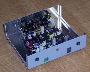
![]() After considering the official NCE Smart Booster upgrade path, I decided take a slightly different route. Instead of having a few large boosters and a large number of cutouts for sub-districts, I decided to build more smaller boosters based upon the MERG NB1B design, each rated at 3 amps, and dispense with sub-district cutouts. This would save me the hassle of ensuring my sub-district breakers tripped out before their boosters and, all things considered, I believe that overall costs should not be very different.
After considering the official NCE Smart Booster upgrade path, I decided take a slightly different route. Instead of having a few large boosters and a large number of cutouts for sub-districts, I decided to build more smaller boosters based upon the MERG NB1B design, each rated at 3 amps, and dispense with sub-district cutouts. This would save me the hassle of ensuring my sub-district breakers tripped out before their boosters and, all things considered, I believe that overall costs should not be very different.
It is a simple “back to basics” 3 amp booster with no frills, tailored to my needs, and uses a commercial switch-mode power supply unit. The chief benefit of this approach is the cost, I built each one for just under £10 (plus the metal case and the connectors) and the PSU cost me £11.
I had the opportunity to buy a second-hand NCE PowerPro 5 amp system and this will feed the loco shed and main line junction. I will be dividing the rest of the layout into three more power districts, the passenger and goods lines with their loops, and the branch line. These distributed boosters will use the same control bus that my MERG accessory decoders use, thus there will be no additional wiring around the layout.
However, events took an unexpected turn as described here.
Nearly every website and “authority” I have read talks about the need to measure the stall current of your motors to determine the power capacity of your decoders and boosters. I disagree. When did you last manage to actually stall an engine out on the running line? Pretty well every engine I’ve ever had running will start to slip if you try to make it pull too many wagons. It is simply not possible to get enough weight on the driving wheels to stop them spinning, even with traction tyres, and the current drawn when spinning is slightly less than when pulling at maximum load. All modern decoders are protected against overload so, if you did manage to stall a motor, the decoder would shut down safely. So I disregard stall current and don’t even try to measure it. Besides, putting 12 volts (or more) across a stalled motor can seriously harm its health!